


12 V / 24 V winding review
Choose the winding around the system supply and loaded operating point.
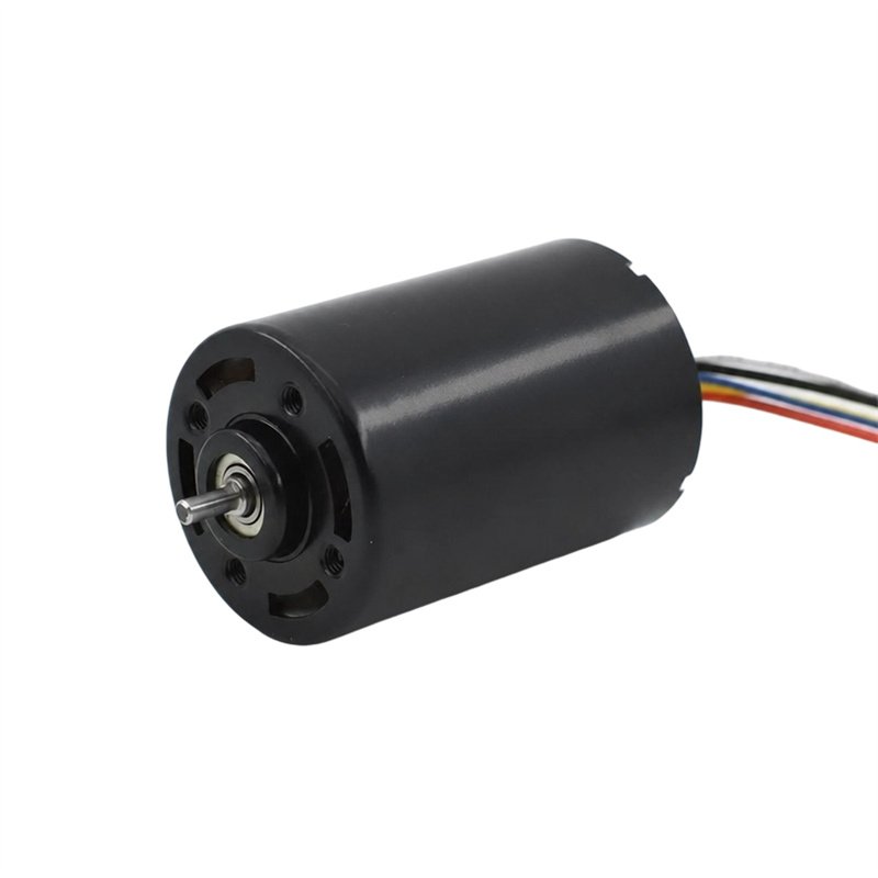
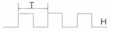
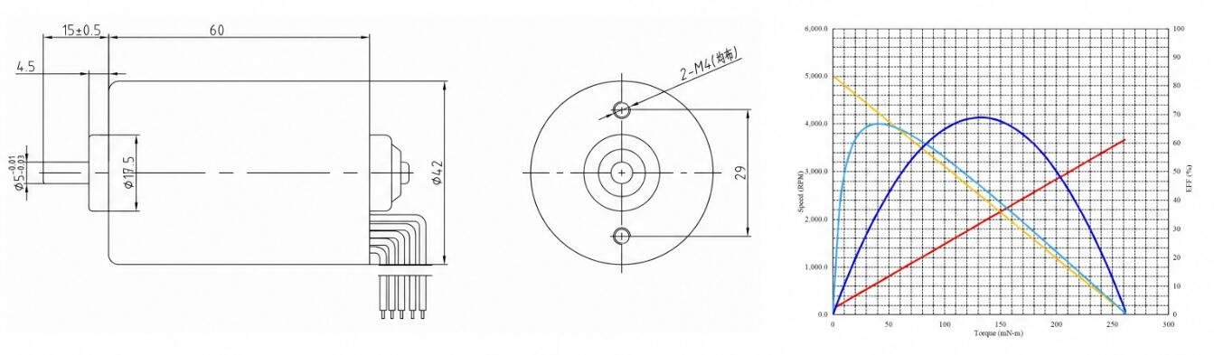
A 42 mm brushless DC motor family with configurations for 12 V and 24 V systems. Review the PWM, direction and feedback interface together with the chosen driver and operating point. Available references are retained below; request the datasheet and approved drawing for the selected configuration, including the items marked for confirmation, before sampling or ordering.
OEM supply · Configuration-specific winding and mechanical interface
| Model | Rated supply V | No-load speed rpm | On-load speed rpm | On-load torque N.m |
|---|---|---|---|---|
| 4260BL-12V-5000R | 12 | 5000 | 4000 | 0.048 |
| 4260BL-24V-5000R | 24 | 5000 | 4000 | 0.052 |
Select the winding and driver together; compare loaded speed and torque at the stated supply.
Performance and dimensions are subject to the selected winding, reduction ratio where applicable, drawing and agreed test conditions. Please confirm the current configuration with Hongyang before ordering. On-load current is omitted pending confirmation of a source discrepancy.
| Detail | Status and required confirmation |
|---|---|
| Loaded current for the selected winding | To be confirmed. Conflicting source current references are omitted. Request the current approved performance sheet. |
| Wire / interface | Function |
|---|---|
| Red | Motor + |
| Black | Motor - |
| White | CW / CCW |
| Blue | PWM |
| Yellow | FG, source-labelled 6 PPR |
The available photographs and technical references are shown below. Confirm the following details for the selected configuration before sampling or ordering.
The selected drawing controls shaft, mounting and tolerance details. Any lettered dimensions without a value are specified for the chosen build.
Use the connection reference as a starting point for the wiring drawing. Agree the supply, signal levels and connector pinout for the selected configuration.
Feedback availability and signal details depend on the configured assembly.
42 mm brushless platform with PWM, direction control and FG feedback. Use an existing configuration as the starting point, then review the interfaces that connect it to your equipment.
Choose the winding around the system supply and loaded operating point.
Use the installation drawing to define the shaft and fixing arrangement.
Review supply, current limits and control signals as a system.
Agree feedback format, wiring and connector details for the chosen build.
Use the intended system voltage and the required speed and torque under load.
Check the shaft profile, projection, fit and fastener positions against your assembly.
Evaluate the motor in the intended enclosure and operating cycle.
Agree current, speed, direction and any feedback checks before sample approval.
Send this series name, the full variant if selected, the installation drawing and required working point.
Check fit and performance in your equipment. Record the supply, load, duty and test method.
Agree the drawing revision, model code, acceptance requirements and order quantity before release.
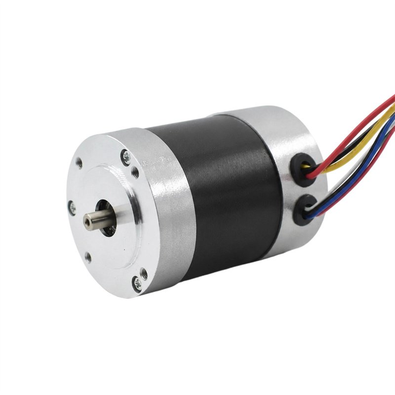
Review the motor dimensions and control interface for your OEM drive system.
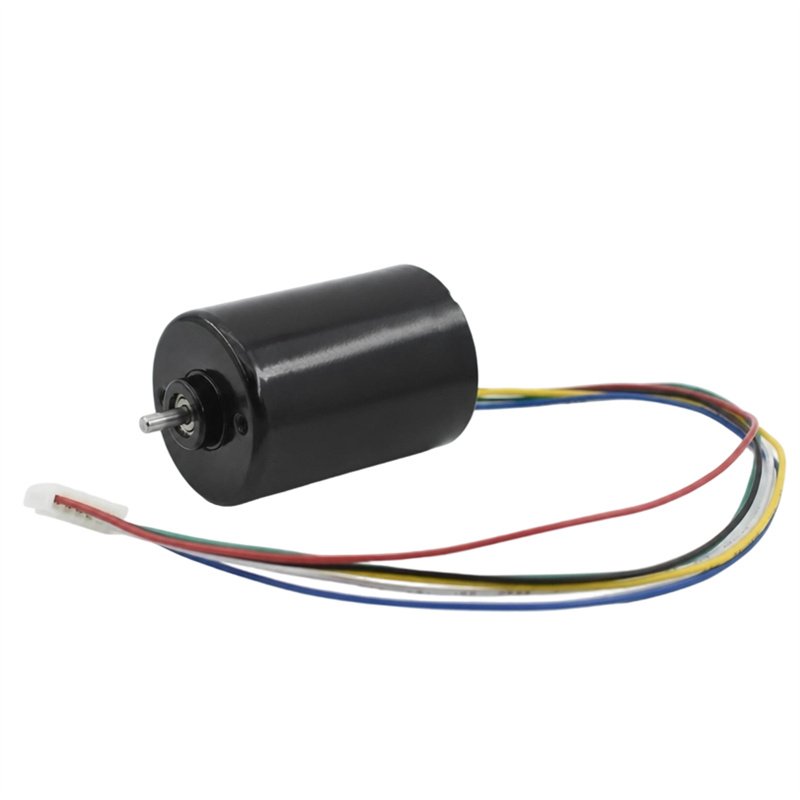
Review the motor dimensions and control interface for your OEM drive system.
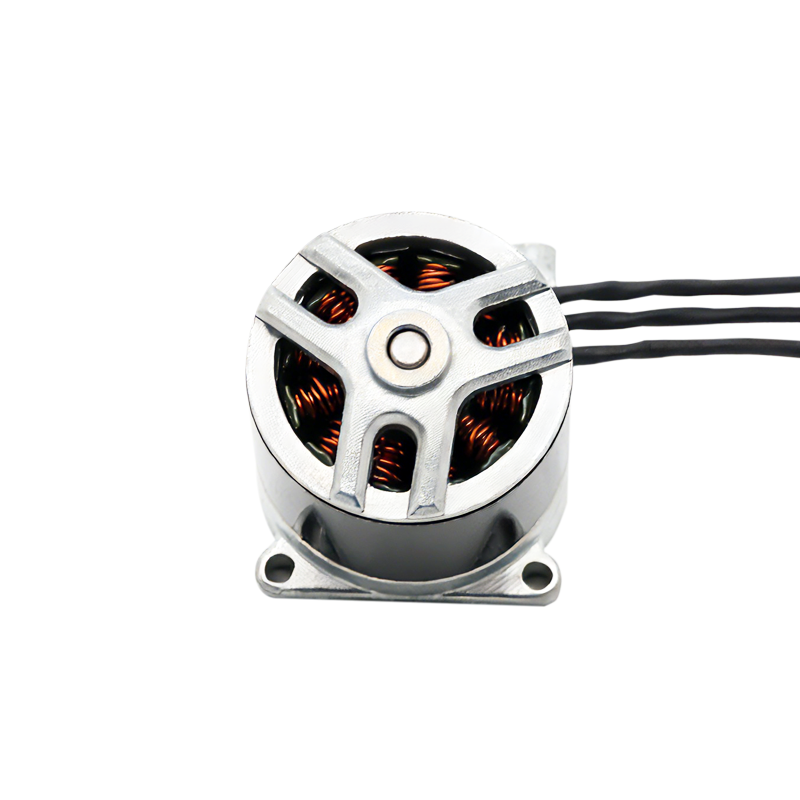
Review the motor dimensions and control interface for your OEM drive system.
Details to confirm
Send your preferred model or the working point, installation drawing and expected quantity.
A drawing, reference motor or application brief is a useful starting point.
Open the full inquiry page →Tell us about your equipment and the motor you need.