


Torque through the cycle
Describe startup, normal operation and short load peaks. State whether the figures refer to the motor shaft or the tool output.
Start with the tool’s load, battery supply and installation space. Hongyang reviews brushed motor platforms and project-specific configurations for electric fastening and cutting equipment.
A motor must fit the handle or housing, work with the transmission and deliver the required output over the tool’s operating cycle. A no-load speed alone does not describe the fastening or cutting task.
For an OEM project, define the working point at the motor shaft and the tool output. Include starts, reversals, short overloads, pauses and the available battery voltage range. These details guide the winding, mechanical interface and sample evaluation.
Explore OEM / ODM DevelopmentDescribe startup, normal operation and short load peaks. State whether the figures refer to the motor shaft or the tool output.
Include output speed and the transmission ratio. Compare motor configurations at the required loaded point.
Provide nominal, minimum and maximum supply voltage, together with controller and battery current limits.
Share housing space, mounting, shaft projection, bearings and connector constraints.
Record run and rest periods, ambient conditions and the installed enclosure for sample evaluation.
Describe direction changes, torque control, braking and feedback requirements for the complete drive system.
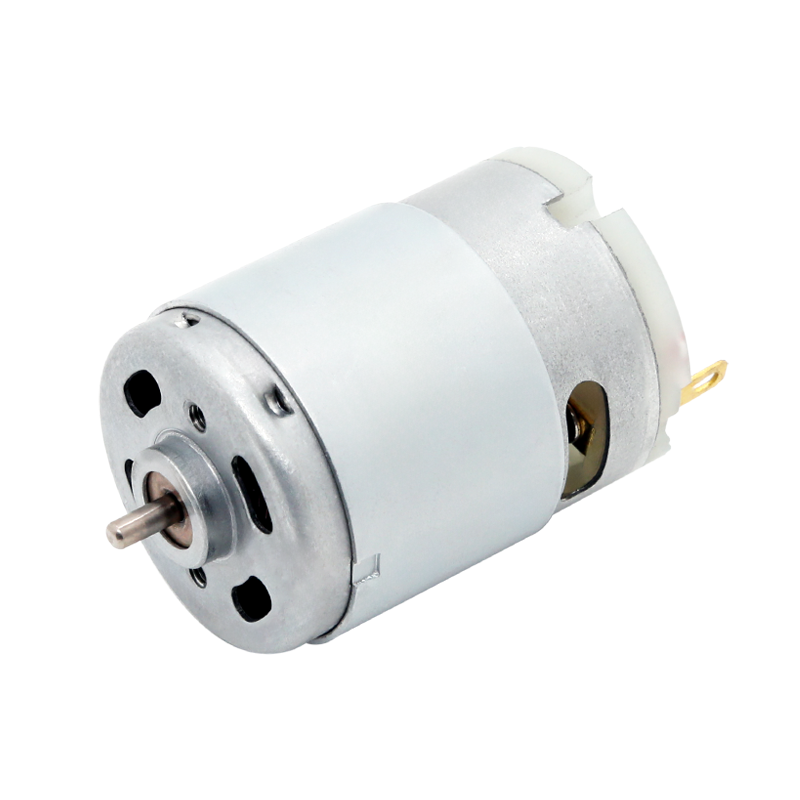
The RS-380 and RS-390 series are part of Hongyang’s electric-screwdriver offering. The RS-380 reference has a 27.7 mm motor diameter and 38 mm body length, excluding the shaft; the magnet shield can change the outside envelope.
Review the winding together with the gearbox, fastening speed and required output torque. For an electronically controlled tool, include the sensing and stopping method so the motor and controller can be evaluated together.
Hongyang’s RS-755 range includes pruning-tool applications. Its published mechanical reference is a 42 mm motor diameter and 60 mm body length, excluding the shaft. Confirm the complete envelope, including any magnet shield and shaft arrangement.
The RS-755 is a starting point for engineering review. Cutting load, blade linkage, reduction, speed and repeated start-stop cycles determine whether a particular winding and assembly are suitable for your tool.
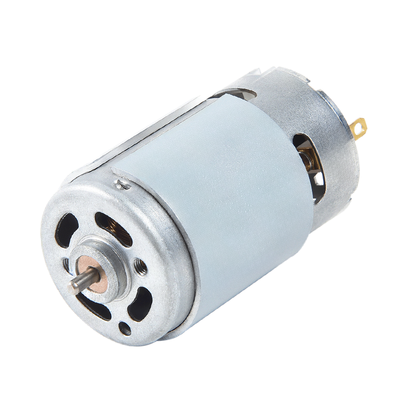
For a packaging-tool development project, send the tensioning, feed or driving sequence and the motor’s role in that mechanism. Include force or torque, cycle time, supply, available space and controller requirements.
Motor selection for this application requires an engineering review. A particular Hongyang model is not specified here as a validated strapping-tool configuration.
Request a Packaging-Tool ReviewRequired force, speed, transmission and mounting.
Starts, reversals, load peaks and time between cycles.
Battery limits, current control and feedback signals.
Define repeatability, heat and endurance conditions.
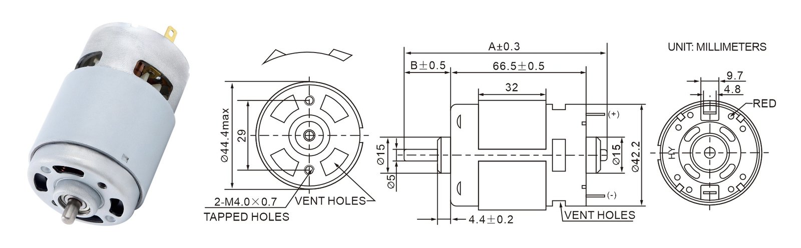
A mechanical drawing establishes shaft, mounting and installation interfaces. A configuration table describes a particular winding or ratio at its stated test point. Keep both tied to the full motor code.
The RS-775 drawing shown here illustrates the information available in our product records. It is a dimensional reference, rather than a tool-specific selection. Your chosen motor is evaluated against the actual transmission, controller and operating cycle.
Compare Product Records| Project stage | What to define | Review output |
|---|---|---|
| Application brief | Tool, load, supply and installation drawing. | Platform and configuration requirements. |
| Engineering review | Winding, shaft, transmission and control interfaces. | Proposed full motor code and drawing. |
| Equipment evaluation | Fit, loaded cycle, current, stopping and temperature. | Recorded results and required changes. |
| Production approval | Approved sample, drawing revision and test conditions. | A common baseline for engineering and purchasing. |
Voltage is only one input. Include loaded speed, torque, duty, transmission, current limits and installation constraints to identify a suitable configuration.
No. They are application starting points. The winding, gearbox or linkage, control system and operating cycle require review and sample evaluation.
Send the complete tool requirement and preferred control approach. The team can review it against the available product range; a specific brushless platform needs its driver and feedback interface defined.
Include the requested changes in your drawing or technical brief. Availability and development scope are assessed for the selected motor structure.
Agree the full motor code, drawing revision, evaluated sample and acceptance conditions, together with order quantities and documentation requirements.
Include the tool type, proposed motor or reference sample, battery range, loaded speed and torque, installation space and expected quantity.
Describe the operating cycle and any particular control or validation requirements. Mention a drawing in your message so the team can arrange the technical file exchange.
Your inquiry is handled under our Privacy Policy.