


Reduction ratio and output speed
Match the reduction ratio and output speed to the required continuous and peak load.

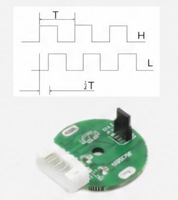
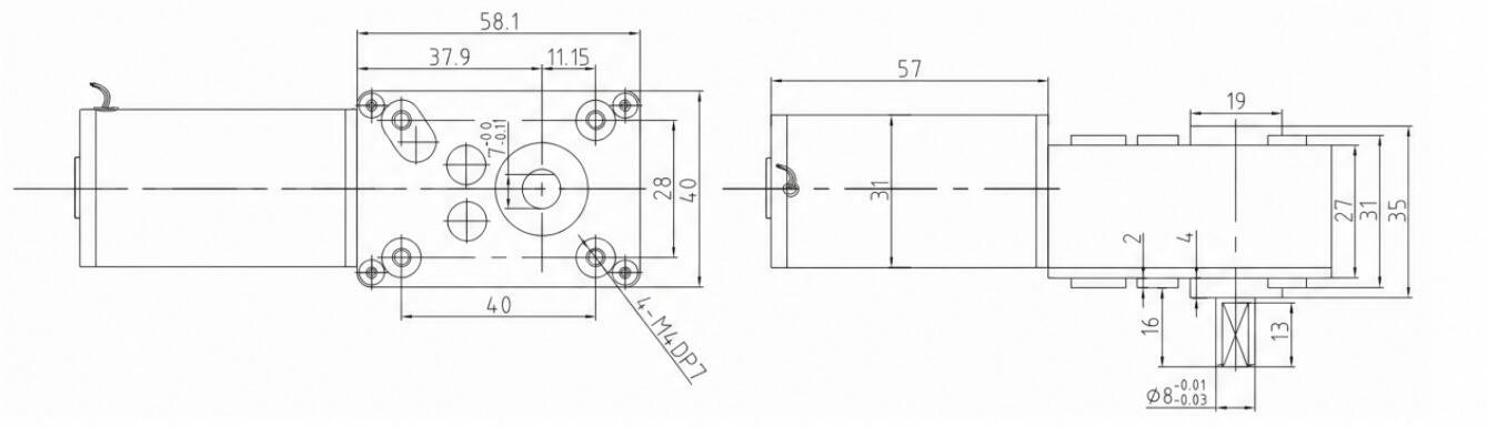
A right-angle worm geared motor family with reduction-ratio options and an optional feedback reference. Review mounting space, output speed, load torque and power-off holding requirements together.
OEM supply · Configuration-specific winding and mechanical interface
| Model | Rated supply V | Reduction ratio | Gear stages | Gearbox length mm | No-load output speed rpm | On-load output speed rpm | On-load output torque N.m | On-load current mA |
|---|---|---|---|---|---|---|---|---|
| TJW58FX27i-12V-185.2R | 12 | 27 | 3 | 58 | 185.2 | 148.1 | 0.18 | 500 |
| TJW58FX50i-12V-100R | 12 | 50 | 3 | 58 | 100 | 80 | 0.34 | 500 |
| TJW58FX79i-12V-63.3R | 12 | 79 | 3 | 58 | 63.3 | 50.6 | 0.54 | 500 |
| TJW58FX93i-12V-53.8R | 12 | 93 | 3 | 58 | 53.8 | 43 | 0.63 | 500 |
| TJW58FX122i-12V-41R | 12 | 122 | 3 | 58 | 41 | 32.8 | 0.83 | 500 |
| TJW58FX167i-12V-29.9R | 12 | 167 | 3 | 58 | 29.9 | 24 | 1.13 | 500 |
| TJW58FX213i-12V-23.5R | 12 | 213 | 3 | 58 | 23.5 | 18.8 | 1.45 | 500 |
| TJW58FX263i-12V-19R | 12 | 263 | 4 | 58 | 19 | 15.2 | 1.61 | 500 |
| TJW58FX311i-12V-16.1R | 12 | 311 | 4 | 58 | 16.1 | 12.9 | 1.9 | 500 |
| TJW58FX407i-12V-12.3R | 12 | 407 | 4 | 58 | 12.3 | 9.8 | 2.49 | 500 |
| TJW58FX556i-12V-9R | 12 | 556 | 4 | 58 | 9 | 7.2 | 3 | 500 |
| TJW58FX710i-12V-7R | 12 | 710 | 4 | 58 | 7 | 5.6 | 3 | 500 |
Published configuration codes use the TJW58FX family. Confirm the full configuration code against the selected drawing when ordering this 4058WG31S platform.
Compare reduction ratio, output speed, load torque and gearbox length as one configuration.
Performance and dimensions are subject to the selected winding, reduction ratio where applicable, drawing and agreed test conditions. Please confirm the current configuration with Hongyang before ordering.
| Wire / interface | Function |
|---|---|
| Encoder option | A / B dual channel; source-labelled 5 V, 12 PPR |
The selected drawing controls shaft, mounting and tolerance details. Any lettered dimensions without a value are specified for the chosen build.
Use the connection reference as a starting point for the wiring drawing. Agree the supply, signal levels and connector pinout for the selected configuration.
Feedback availability and signal details depend on the configured assembly.
Right-angle output with 12 ratio references and an encoder option. Use an existing configuration as the starting point, then review the interfaces that connect it to your equipment.
Match the reduction ratio and output speed to the required continuous and peak load.
Define shaft engagement, external loading, orientation and mounting dimensions.
Review optional A/B feedback, signal supply and mechanical compatibility for the selected assembly.
Specify the operating cycle and validate power-off holding for the complete mechanism and load.
Select output torque and speed together; allow for starting and peak loads.
Check shaft loading, support, orientation and mounting envelope.
Define run time, reversing cycles and the required control behavior.
Holding depends on the ratio, load and complete mechanism. Validate it for the application; it is not a safety brake.
Send this series name, the full variant if selected, the installation drawing and required working point.
Check fit and performance in your equipment. Record the supply, load, duty and test method.
Agree the drawing revision, model code, acceptance requirements and order quantity before release.
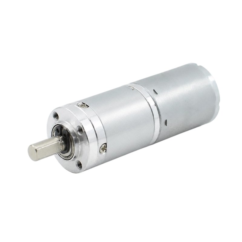
Compare ratio-specific output data, gearbox dimensions and mounting requirements.
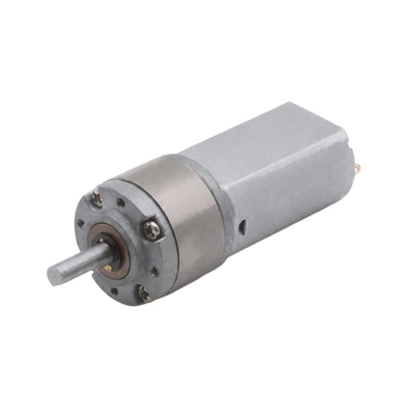
Compare ratio-specific output data, gearbox dimensions and mounting requirements.
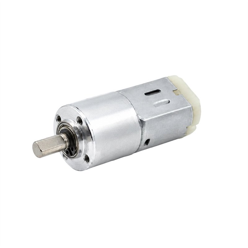
Compare ratio-specific output data, gearbox dimensions and mounting requirements.
Send your preferred model or the working point, installation drawing and expected quantity.
A drawing, reference motor or application brief is a useful starting point.
Open the full inquiry page →Tell us about your equipment and the motor you need.