


Winding and operating point
Match the voltage, loaded speed and torque to the equipment duty.
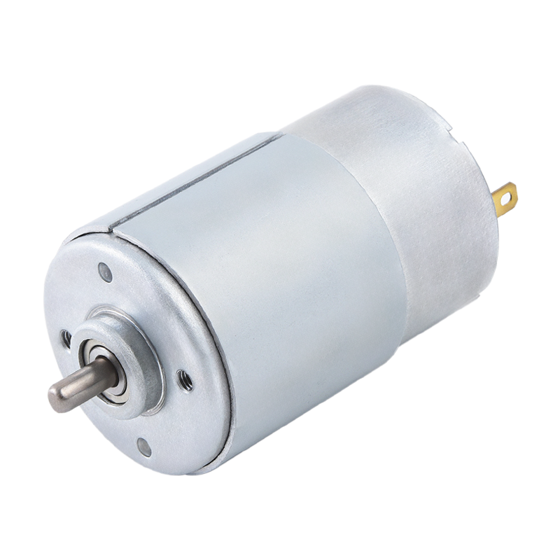
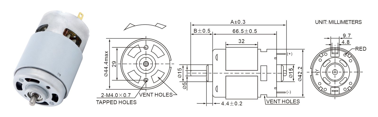
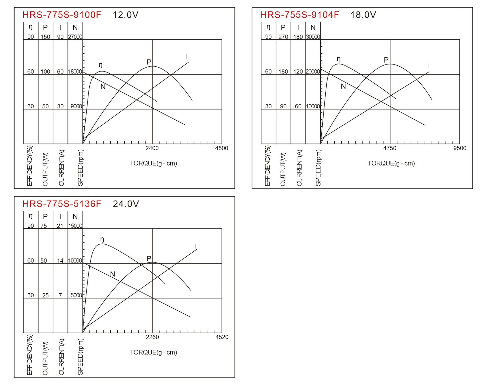
A brushed permanent-magnet DC motor family for OEM equipment. Compare winding variants, review the installation drawing and choose the operating point around the intended load.
OEM supply · Configuration-specific winding and mechanical interface
| Model | Nominal supply | No-load speed rpm | No-load current A | Speed at maximum efficiency rpm | Torque at maximum efficiency mN-m | Output at maximum efficiency W | Maximum efficiency % |
|---|---|---|---|---|---|---|---|
| HRS-775S-9100F | 12.0V CONSTANT | 18800 | 2.00 | 16160 | 66.05 | 111.7 | 76.0 |
| HRS-775S-9104F | 18.0V CONSTANT | 21600 | 2.50 | 19200 | 102.9 | 206.8 | 69.7 |
| HRS-775S-5136F | 24.0V CONSTANT | 10300 | 0.70 | 9010 | 55.37 | 52.21 | 78.0 |
Each row is one published configuration. The maximum-efficiency point and the stall point describe different test conditions.
Maximum-efficiency values are not continuous-duty ratings. Use the full suffix when requesting samples.
| Model | Operating voltage range V | Current at maximum efficiency A | Stall current A | Stall torque mN-m |
|---|---|---|---|---|
| HRS-775S-9100F | 6.0 - 12.0 | 12.30 | 75.4 | 470.4 |
| HRS-775S-9104F | 12.0 - 24.0 | 16.50 | 128.5 | 926.1 |
| HRS-775S-5136F | 18.0 - 30.0 | 2.79 | 17.4 | 441.9 |
One legacy curve label contains a 755S/775S typographic discrepancy. Use the complete winding code in the configuration table and request the matching curve for your selected build.
The selected drawing controls shaft, mounting and tolerance details. Any lettered dimensions without a value are specified for the chosen build.
Three HRS-775S winding references for high-speed direct-drive equipment. Use an existing configuration as the starting point, then review the interfaces that connect it to your equipment.
Match the voltage, loaded speed and torque to the equipment duty.
Specify projection, diameter and a round, flat or other required shaft profile.
Review the bearing, rotation and terminal arrangement for your assembly.
Share noise, electrical interference and control requirements with the project brief.
Use the intended system voltage and the required speed and torque under load.
Check the shaft profile, projection, fit and fastener positions against your assembly.
Evaluate the motor in the intended enclosure and operating cycle.
Agree current, speed, direction and any feedback checks before sample approval.
Send this series name, the full variant if selected, the installation drawing and required working point.
Check fit and performance in your equipment. Record the supply, load, duty and test method.
Agree the drawing revision, model code, acceptance requirements and order quantity before release.
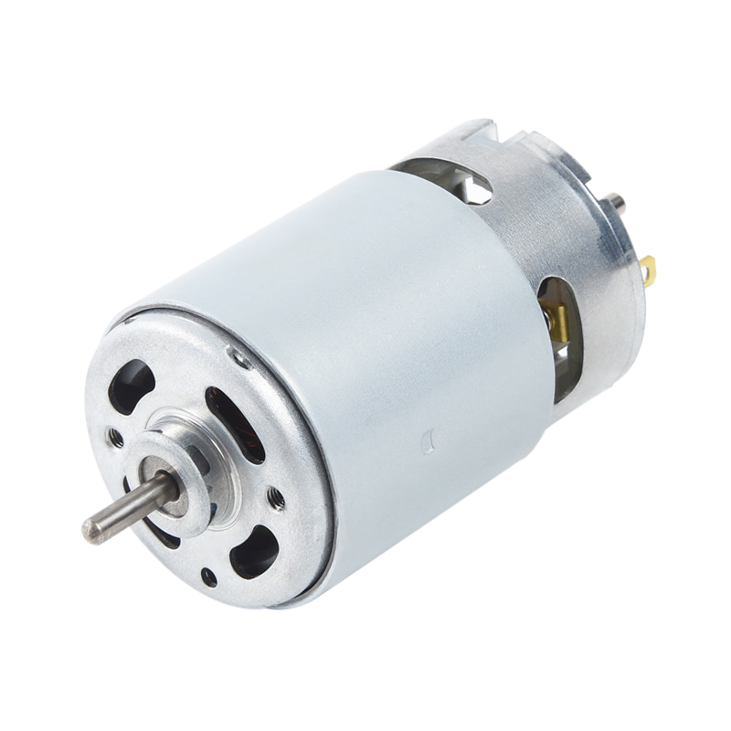
Compare winding references, shaft dimensions and mounting details for your OEM equipment.

Compare winding references, shaft dimensions and mounting details for your OEM equipment.
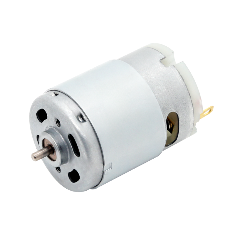
Compare winding references, shaft dimensions and mounting details for your OEM equipment.
Send your preferred model or the working point, installation drawing and expected quantity.
A drawing, reference motor or application brief is a useful starting point.
Open the full inquiry page →Tell us about your equipment and the motor you need.